| Description | Related Tools | |||
|
Toggle All |
||||
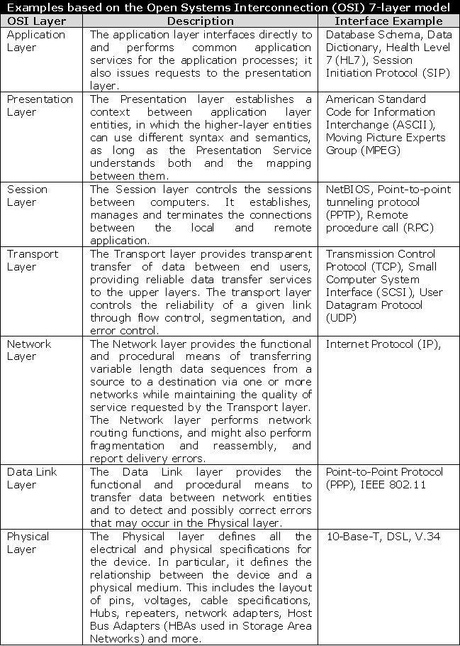
Interfaces are documented using interface control documents (ICD) that describe the system's interfaces as well as any rules for communicating with them. ICDs help ensure compatibility between system segments and components and are often considered key elements of effective system design and development. The purpose of the ICD is to clearly communicate all possible inputs and outputs from a system for all potential actions whether they are internal to the system or transparent to system users. An ICD may describe the system interfaces to the lowest physical elements (circuits, voltage, watts, etc) to the user interface or any subset thereof. The level of detail included in any ICD is dependant upon the requirements of the stakeholders to successfully deliver on project requirements.
ICDs define for the development team system inputs, outputs, internal interfaces, and interfaces between other systems, subsystems and/or users. An ICD should only describe the interface itself and not any characteristics of the systems using it. An ICD should also not include anything about the meaning or intended use of the data. Any features, functions, or logic supporting the system interface should be outlined within separate design and/or specification documents. Defining an ICD in this way allows other teams to develop connecting systems without concern of how the data is treated by the other system. This allows development teams to work without the requirement of knowing the business logic or technical aspects behind the system and allows for modularity that leads to easy maintenance and extensibility of systems.
- Description of interface and interface types. For system development, this may include information such as data type, size, format, measures, etc
- Description of commands and parameters that pass between systems
- Description of how systems communicate with subsystems
- Description of how systems communicate with external systems
- Description of how systems communicate with its users
- Description of how systems interprets external commands and what responses/behaviors are expected
The Federal Enterprise Architecture (FEA) Reference Model contains components that reference many of the items that should be considered when defining ICDs. Some of these items include:
- Interfaces between systems and their users
- Levels of access required by the application and other systems
- End-to-end management of communication sessions between systems and system components
- Hardware, operating system, other software, network protocols, etc that provide or request information
- Data storage, modification, and extraction of information from databases and any required interfaces
- Physical devices that provide the computing and networking within and between systems
- Security methods for protecting information and systems and how such policies/mandates may affect system interfaces
- Connections between the system, users, other systems, and peripherals
- Method for enforcing business rules
- Structure, elements, objects, and properties of data to be exchanged
- Methods in which data is transferred and represented in and between systems and how data is discovered and shared
- Communicating, transporting, and exchanging information through common dialogs or methods
An ICD also allows project teams to leverage other systems by providing developers with the information necessary to build add-on or complementary applications or to simply interface with existing systems. Some examples of interfaces where an ICD may be required include:
- Active Stakeholder Participation - Access is needed for users that have the authority and ability to provide information regarding the system and interfaces being built
- Review and Approve - Review the interface and design documents for precision, completeness, and usability
- Standardize - Whenever possible a project team should consider using an industry recognized standard for system interfaces
- Clearly Documented - Interface details should be clearly documented in the form of an interface control document and supporting system specifications should be documented in the form of a system design document
- Rationale - Document rationale behind design decisions and tradeoffs
- Other Interfaces - Systems and devices have varying interfaces. Understand any required system interfaces prior to design. This may include hardware, software, network, devices, etc
- Verify - Verify all models to ensure they fulfill the functional requirements
- Tradeoffs - In most instances there are a number of ways to accomplish the same action. Be aware of the tradeoffs of selecting one approach as opposed to another and how the effects of that decision may propagate throughout the system
- Guidelines - Define and document modeling guidelines such as recording of assumptions, constraints, issues, approaches, documentation, templates, and notations
- Business Process Specification - Define the intended future state of business processes
- Functional Specification - Define the functional part(s) of the system being developed, external relationships, interaction with the user and other system elements
- Logical Specification - Define the internal logic of the system explaining how it operates
- Conceptual Data Model - Models the underlying business irrelevant of technology
- Logical Data Model - Translates the conceptual model into a structure that can be implemented, by describing the data in as much detail as possible, without regard to how it may be physically implemented
- Physical Data Model - Specifies how to physically implement the logical design by specifying items such as tables, columns, formal relationships between data and tables, etc
- Evaluation - Validates the effectiveness of the models that were developed. This is usually accomplished via user feedback
- Verification - Verify each step within each model to ensure traceability to requirements that delivers the expected system functionality